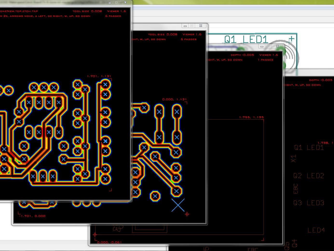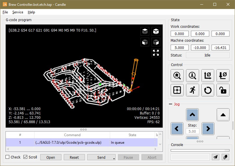

Or add the shape you want onto the PCB edge then delete the outer edge line so it becomes a cut-out. This is right at the corner shown in the picture, if you used the fixture. Make sure your bit is as close to the lower left hand corner of your board, (0,0,0) before sending.

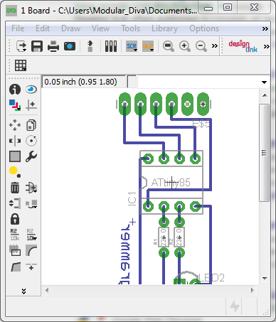
Here is a photo about my crap drawing where I selected with green drawing what I wish to remove. I have found the easiest way to put a cut-out on the PCB edge is just modify the PCB outline shape using the Split tool. If you used Eagle+FlatCAM without auto-level, you can use your preferred gcode sender to send the code you generated in FlatCAM to the X-Carve. I don't wanna remove the whole unused copper from the pcb, that would be too much time-consuming.

So, I'm trying to find a solution how to remove the copper completely around the power traces.ĭoes somebody have a clue how to achieve this? This could be increased and decreased but when it comes to main AC230v that is not enough maybe. This will create a number of gcode files in the specified output directory. run pcb-gcode C:gcodemyboard.or similar on the Eagle command prompt. I faced with a huge problem when I was using power traces on my pcb for feeding main AC/230v through a relay.Īctually, when we mill our pcb on cnc, the copper what is let's say not used ( on chemical etching it would be removed ) it will be left on the board, just a fraction of mm wide gap will be milled between the traces. To run the script, open up your board layout in Eagle then enter. So, I make most time my proto pcb's with my cnc router.įor generating the gcode I use the pcb-gcode upl for Eagle. If admins think this post should not be here pls. Sorry Autodesk for this post, It doesn't think this is related to be here but here are peoples who maybe can help me. Generation of Footprint from Schematic 1.creating new part from existing library part 1.


 0 kommentar(er)
